Special attention: The scattered parts of the electronic product need to be hands -on capabilities, and the novice shoots carefully; (if it is unavailable after welding, the store does not support after -sales and does not provide technical services, it is expected to understand);
1. The working principle of the circuit
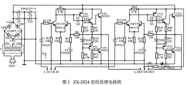
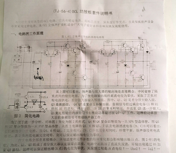
As can be seen from the figure below, the output end of the speaker and amplifier is directly coupled, and the output capacitance of DC is eliminated in the middle. In order to make the DC potential of the circuit output end zero, the positive and negative symmetrical power supply is used.Waiting for measures.In Figure 1, VT I and VT2 are differential enlarged input levels, VT3 is incentives, and VT4 ~ VT7 is a composite complementary output level.The audio signal is sent to the base of VT i after the coupling capacitance C 1 and R i. After amplifying, it is output by the collector of the VT I and sent to the VT3 further. The incentive signal of the VT3 episodes output to promote the power output level VT4 ~VT7 work, so the audio signal after power enlarged can promote speaker work.
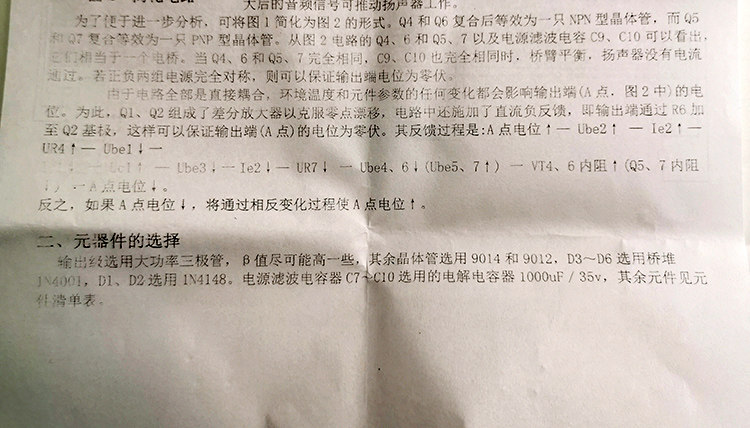
In order to facilitate further analysis, Figure 1 can be simplified into Figure 2.After the VT4 and VT6 composite are equivalent to a NPN crystal tube, and the VT5 and VT7 composite are equivalent to a PNP transistor.From the VT4, 6 and VT5, 7 and power filter capacitors C9 and C10 in Figure 3 circuits, it can be seen that they are equivalent to a bridge.When VT4, 6, VT5, 7 are exactly the same, and C9 and C10 are exactly the same, the bridge arm is balanced, and the speaker does not pass through.If the two sets of power supply are completely symmetrical, the output end potential can be guaranteed to be zero.
Since the circuit is all directly coupled, any change in the ambient temperature and component parameters will affect the potential of the output terminal (point A, in Figure 2).To this end, VT 1. VT2 forms a differential amplifier to overcome zero drift, and DC feedback is applied to the circuit, that is, the output end is added to the base of VT2 through the R6.Vile.Its feedback process is: point A potential↑—ube2↑—ie2↑—ur4↑—ube l↓One IC L↓One UC 1↑—ube3↓One IE2↓—ur7↓One Ube4, 6↓(Ube5, 7↑) One VT4, 6 internal resistance↑(VT5, 7 internal resistance↓) A point A Power Power↓EssenceConversely, if point A potential↓, Point A will be used to use the opposite change process↑Essence
2. Installation and production
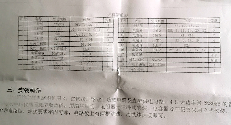
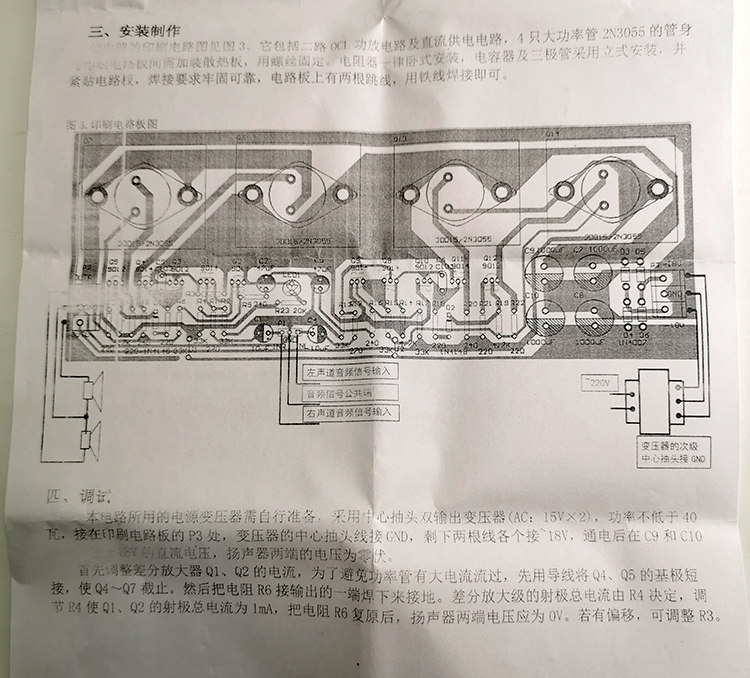
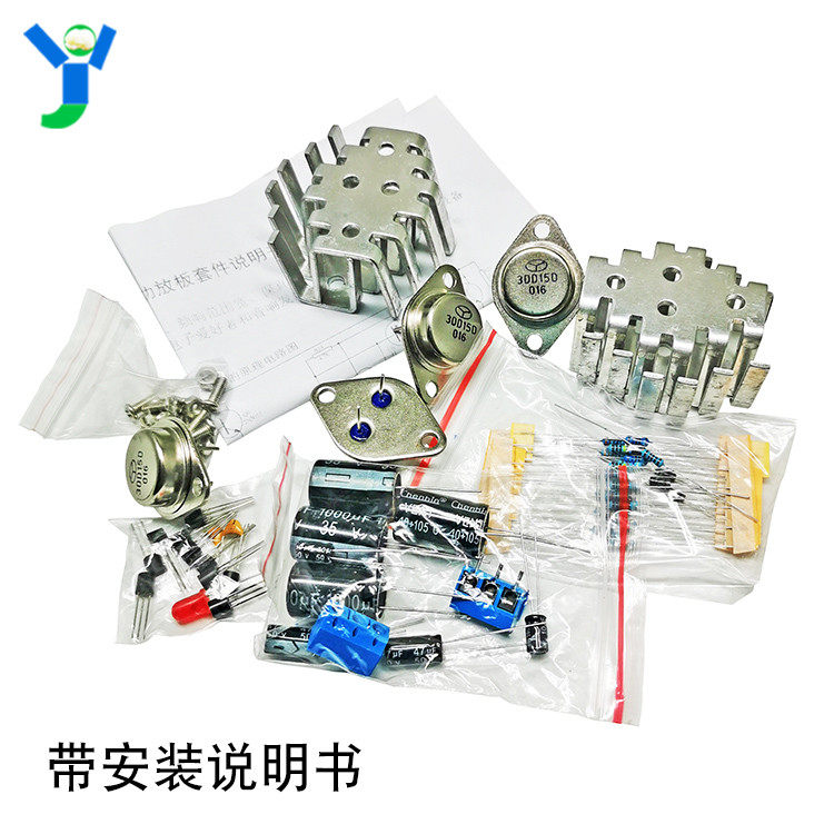
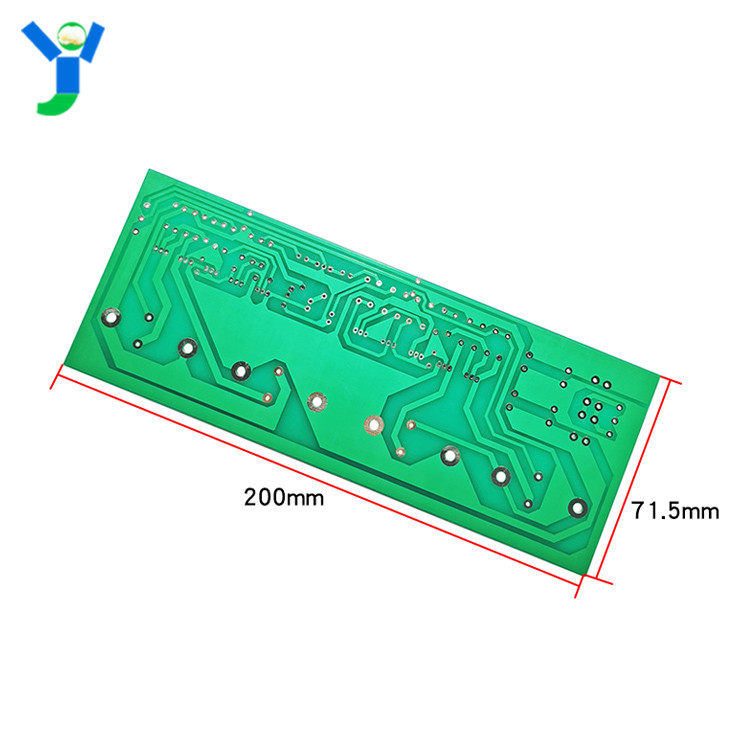
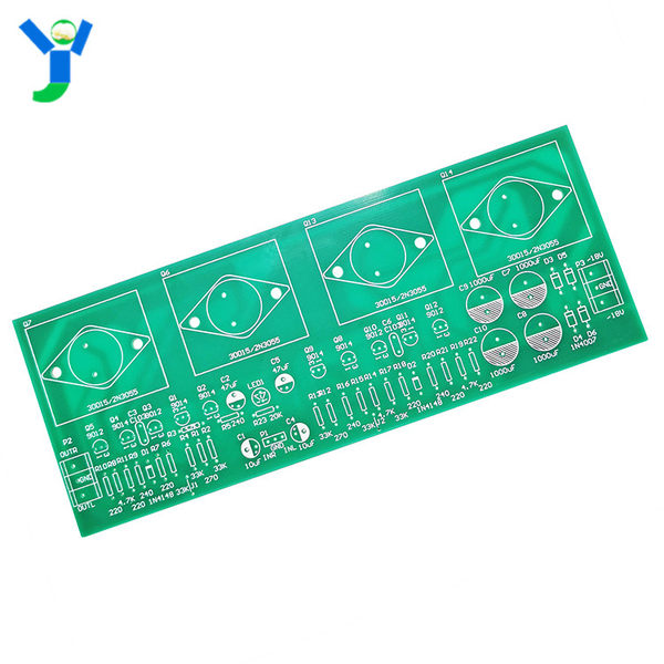
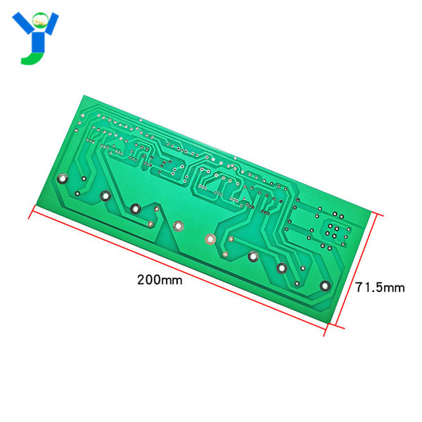
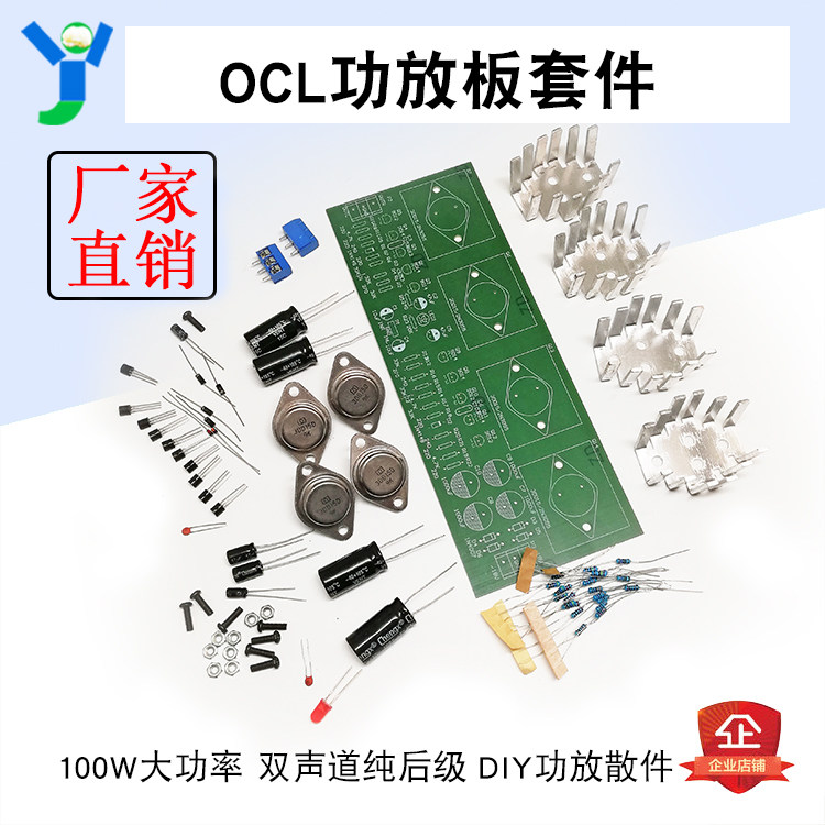
The printing circuit diagram of this circuit is shown in Figure 3.It includes the second -road OCL amplifier circuit and DC power supply circuit. The pipe body and printing circuit board of 4 high -power tube 2N3055 need to be installed with a heat sink and fix them with screws.The resistor is all -duty installation. The capacitor and triode are installed with vertical installation and close to the circuit board. The welding requirements are firm and reliable. There are two jump wires on the circuit board.
3. Debug
The power transformer used in this circuit needs to be prepared by itself.×2), the power is not less than 40 watts, connected to the AC ~ and where you are connected to the printing circuit board.±1 8V DC voltage, the voltage at both ends of the speaker is zero.
First adjust the current of differentials VT L and VT2. In order to avoid large current flows through power pipes, first use wires to shorten the bases of VT4 and VT5 to intercept VT4 ~ VT7.Then welded the output of the resistance R6 and welded.Total currents at differential amplification are determined by R4. Adjusting the total current of the R4 to 1mA of VT 1 and VT2 is 1MA. After the resistance R6 is restored, the voltage ends of both the speaker should be O.If there is offset, you can adjust R3.
Features:
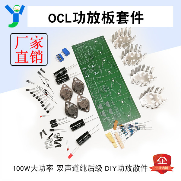
Full separation element, four high -power triode, two three -dimensional sound, each power can reach 100W.
This amplifier uses a typical OCL circuit. It has the advantages of high stability, wide frequent range, and good preservation. This circuit is often used in Gao Chuanzhen's sounding equipment.This OCL stereo pitch is suitable for the majority of electronic enthusiasts and audio enthusiasts.